
USocket – USB controlled Socket with PIC18F4550
Introduction
The idea of this project is to control (switch off/on) two power sockets with a computer by using its USB port. I’ve chosen USB in first place because I wanted to experiment with the PIC18F4550 microchip’s microcontroller, and secondly because the power supplied by this port (500mA) is enough to activate a relay without any additional power supply.
The firmware is based in SIXCA USBDAQ which is in turn based on microchip’s CDC sample. USBDAQ is extremely easy to use. It implements a very simple set of ASCII commands to turn on/off the digital outputs, that I use to control the two relays. I just needed to adjust the bMaxPower in order to negotiate the 500mA with the host, and I also changed the vendor ID and the name of the device to USocket.
I’ve also made the schematic and board design of the circuit with Eagle, but I never used it since I made it on a strip board :D, so if you plan to use it please double check everything before.
The whole project including PIC firmware and Eagle files is available for download. You are free to use or modify it as you like, but please verify Microchip’s CDC sample license if you plan to use it for commercial applications.
Disclaimer: This project involves high voltage electricity. You should not attempt this project unless you are comfortable with basic concepts of AC and DC electricity, induction, and reading circuit schematics. You and your adult supervisor are responsible for your safety when doing this project!
Advice: Despites the high voltage part of the circuit is virtually isolated from the controller circuit by relays, these devices always represents a risk of mechanical failure and they can possibly damage your equipment or even cause physical injuries, so we (the author or the webmasters) are not responsible of any lose or damage.
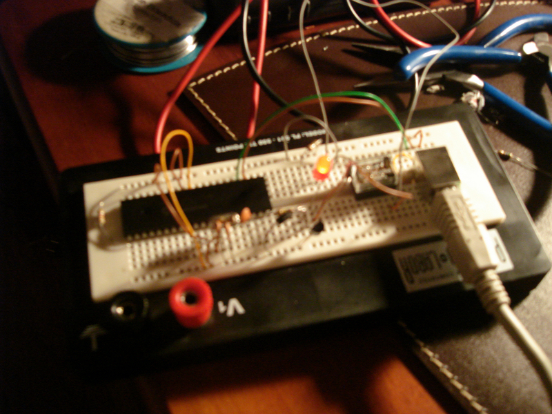
The Circuit

Pretty much the same as USBDAQ but two (identical) sub-circuits were added to control the relays. A Darlington-transistor is used to protect the hardware. Once again, the idea was obtained from the web (thanks to google) and here is the link to the original article.
The PCB is divided in 3 little boards, for commodity and socket case space issues. (I’ve used only 2 strip boards in the actual prototype).

List of materials:
- IC1 – PIC16F4550 Microchip’s micro-controller (datasheet)
- Q2 – Crystal 20Mhz
- R1 – Resistor 4.7K
- R2 – Resistor 1M
- R3, R5 – Resistors 150
- R4, R6 – Resistors 100K
- K1, K3 – 5v Relays. I’ve used FBR211 by Fujitsu (datasheet)
- D1, D2, D3. D4 – Diodes 1N4004
- Q1, Q3 – BC517 Darlington-transistors (datasheet)
- LED1, LED2 – Regular leds
- C1, C2 – Capacitors 22pF
- C3 – Capacitor 470pF
- X1 – Mini-USB Connector Type B (datasheet)
PIC Firmware
Here is what I needed to modify from the original SIXCA USBDAQ:
I set bMaxPower to 250, which means 500mA. The power provided by hosts and hubs is twice the value of bMaxPower field, but in reality they are likely to allocate either 100 or 500 milliamperes rather than the specified amount.
The file modified is the one that contains the USB descriptor: fw/cdc/autofiles/usbdsc.c
/* Configuration 1 Descriptor */
CFG01=
{
/* Configuration Descriptor */
sizeof(USB_CFG_DSC),    // Size of this descriptor in bytes
DSC_CFG,                // CONFIGURATION descriptor type
sizeof(cfg01),          // Total length of data for this cfg
2,                      // Number of interfaces in this cfg
1,                      // Index value of this configuration
0,                      // Configuration string index
_DEFAULT,               // Attributes, see usbdefs_std_dsc.h
250,                    // Max power consumption (2X mA) 250 = 500mA

...
In the same file I modified the Vendor ID, Product ID and corresponding strings
/* Device Descriptor */
rom USB_DEV_DSC device_dsc=
{
sizeof(USB_DEV_DSC),    // Size of this descriptor in bytes
DSC_DEV,                // DEVICE descriptor type
0x0200,                 // USB Spec Release Number in BCD format
CDC_DEVICE,             // Class Code
0x00,                   // Subclass code
0x00,                   // Protocol code
EP0_BUFF_SIZE,          // Max packet size for EP0, see usbcfg.h
0xAF01,                 // Vendor ID
0xAF0A,                 // Product ID: CDC RS-232 Emulation Demo
0x0000,                 // Device release number in BCD format
0x01,                   // Manufacturer string index
0x02,                   // Product string index
0x00,                   // Device serial number string index
0x01                    // Number of possible configurations
};

...

rom struct{byte bLength;byte bDscType;word string[16];}sd001={
sizeof(sd001),DSC_STR,
'a','l','f','e','r','s','o','f','t','.',
'c','o','m','.','a','r'};

rom struct{byte bLength;byte bDscType;word string[21];}sd002={
sizeof(sd002),DSC_STR,
'A','l','f','e','r','S','o','f','t',' ',
'U','S','o','c','k','e','t',' ','1','.','0'};
And the file driver/win2k_winxp/mchpcdc.inf Windows, to match the new vendor, product ID and description
[DeviceList]
%DESCRIPTION%=DriverInstall, USB\VID_AF01&PID_AF0A
...
;------------------------------------------------------------------------------
; String Definitions
;------------------------------------------------------------------------------
[Strings]
MCHP="alfersoft.com.ar"
MFGNAME="alfersoft.com.ar"
DESCRIPTION="Communications Port"
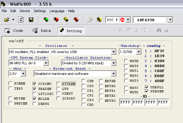
SERVICE="AlferSoft USocket 1.0"Programming the PIC
I’ve used WinPic800 to program the PIC. Here is a screenshot of the parameters I used to program it.
Commands
I didn’t modified any of the USBDAQ commands. They are all available but I only need to use these 4 commands:
- *A01 (activate relay 1)
- *A00 (deactivate relay 1)
- *A11 (activate relay 2)
- *A10 (deactivate relay 2)
All the commands are followed by an enter (chr(13) or ‘\n’).
Installing (Windows)
-
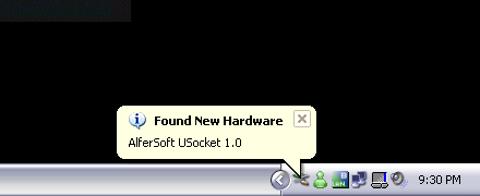
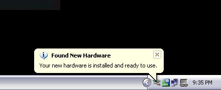
Plug the device into the USB port, the following message will appear in the tray bar.
-
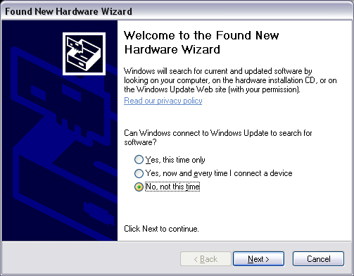
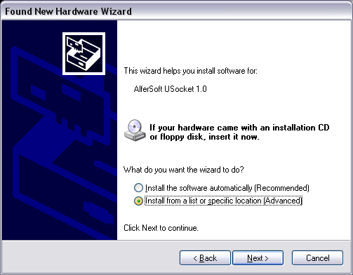
In the first page of the “Found New Hardware Wizard” select “No, not this time” and click Next button.
-
Select the “Install from a list or specific location (Advanced)” option and click Next button.
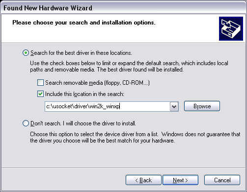
-
Mark the “Include this location in the search:” and browse for the directory where the .inf file is located (driver\win2k_winxp)
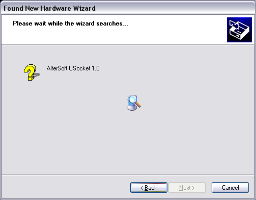
-
This message will appear:
-
And then this one:
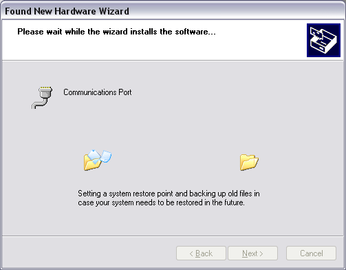
-
When the installation is done press “Finish”
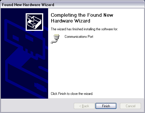
-
After that the hardware is ready to use.
Testing (Windows)
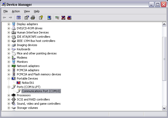
-
Go to the device manager and locate the new COM port added, in my example COM10 was added
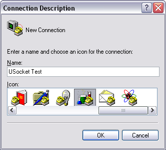
-
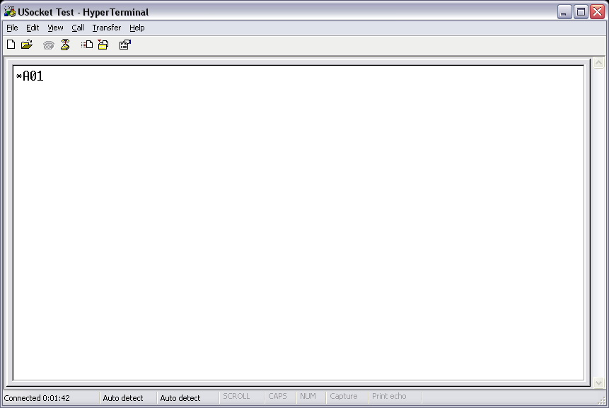
Open Hyperterminal and choose a name for the new conection
-
Select the new COM port
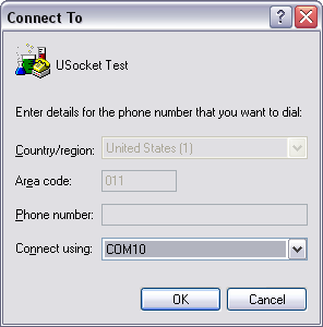
-
Set the Bit rate to 115200
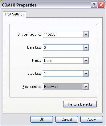
-
This step is optional to see what we are typing on the screen, choose ASCII Setup
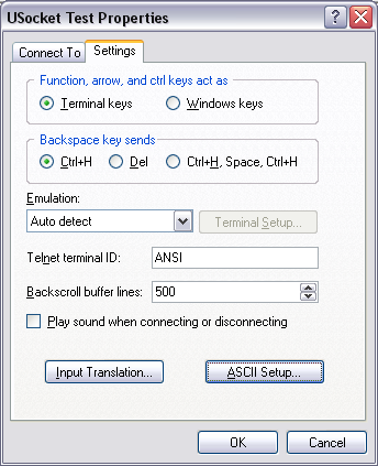
-
Then mark “Echo typed characters locally”
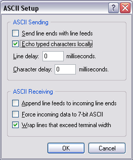
-
Finally connect and type one of the commands
Installing (Linux – Ubuntu)
- Plug it. That’s it! a new device probably called /dev/ttyACM0 will be added by the OS.
Testing (Linux – Ubuntu)
-
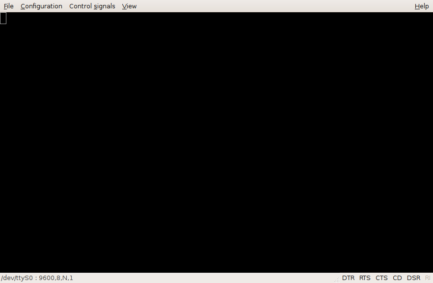
Open gtkterm if you don’t have it installed type “sudo apt-get install gtkterm” from a terminal
-
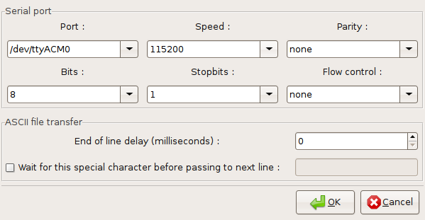
Go to Configuration -> Port, set the port to /dev/ttyACM0, the speed to 115200 and click OK
-
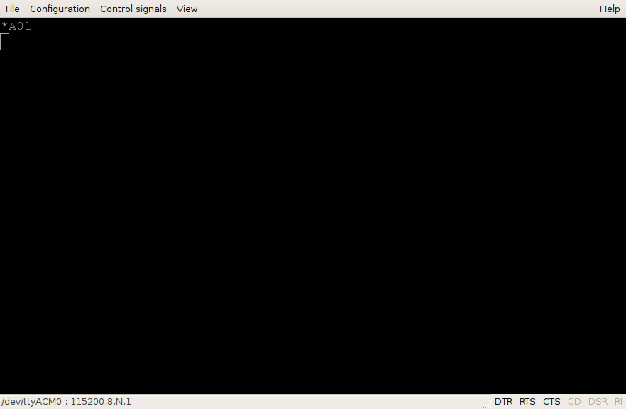
Select Configuration -> Local echo
-
Type the command and press enter
Problem
After I mounted everything in the case a problem appeared, if I plug the USB cable to the computer and then the socket to the wall, the PIC hangs. But it works well the other way round (first plug to the wall and the to the computer). That is probably because the high voltage cables are too close to the PIC and unfortunatelly I’m not an expert in that matter and I don’t know how to fix it except by putting the circuit in a separated box. Experts needed! If you know another way to fix it please let me know!
Pictures


Update
Here is a small modification to read the current relay state: Add two diodes one from pin 19 to 33 and the other from pin 20 to 34. Use the command *B to read the status.

Download
USocket on GitHub, enjoy it!
Comments